Improve the inspection of plastic injection components by industrial tomography
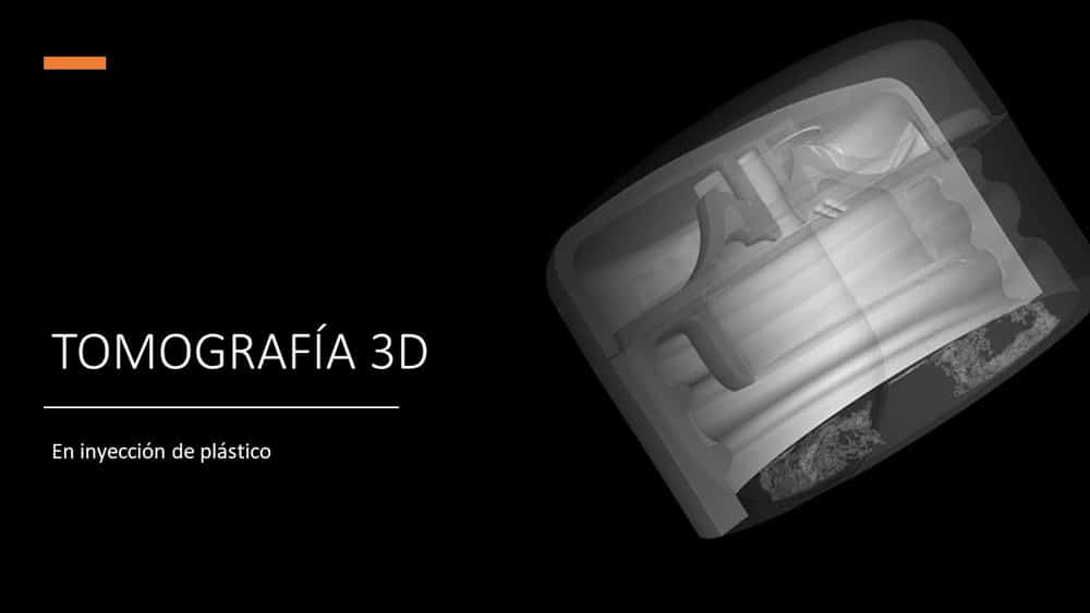
La inyección de plástico es un proceso de fabricación ampliamente conocido, que crea millones de piezas todos los días.
Los termoplásticos y polímeros termo-endurecibles que pasan por el proceso de moldeo por inyección de plástico se utilizan para muchos componentes comunes, como tapas de botellas, contenedores de almacenamiento, equipos médicos, carcasas eléctricas, juguetes ... Hoy en día, este proceso avanzado incluso puede gestionar inyecciones de múltiples materiales para mejorar la densidad, rigidez o para proporcionar colores, transparencia y texturas para una especificación determinada.
Sin embargo y porque es su principal objetivo, las máquinas de moldeo por inyección de plástico han sido diseñadas para producir grandes volúmenes de la misma pieza. Una vez ajustado, todo el proceso debe verificarse periódicamente para mantener las características de los productos terminados. Los componentes de plástico a menudo se evalúan por su apariencia visual, resistencia mecánica e impermeabilidad.
Además, obtener la geometría perfecta para una pieza de plástico deseada es a menudo un camino largo con varios pasos de optimización para el material, la forma del molde y los parámetros que influyen en la solidificación. Incluso si las herramientas de simulación son cada vez más poderosas, muchos factores aún se optimizan con mediciones y análisis realizados en prototipos. La clave para esta industria es reducir el tiempo dedicado a optimizar el proceso para minimizar los plazos de producción.
La tomografía industrial es muy adecuada para componentes de inyección de plástico
Incluso si los métodos de inspección tradicionales, como las mediciones de las máquinas de medición por coordenadas (CMM) o el escaneado óptico, pueden brindar resultados interesantes, es posible que deban completarse con rayos X -CT para muchas aplicaciones.
La tomografía computerizada está particularmente bien adaptada para piezas de plástico debido a la densidad relativamente baja del material común utilizado. La poliamida, el policarbonato, el poliéster, el polipropileno y el polietileno son todos muy fáciles de penetrar por rayos X. Esto significa que obtener las dimensiones internas y externas de las piezas no será un problema para la tecnología de rayos X- CT: sea cual sea el tamaño de la muestra, los resultados obtenidos serán muy precisos y se obtendrán más rápido que con las técnicas convencionales.
A diferencia de otras tecnologías, la tomografía industrial no necesita ninguna preparación particular de la muestra a controlar. Sin spray, sin pegatinas, sin programa de sondas, lo único que debe hacerse antes de iniciar un escaneado es elegir una buena orientación y un utillaje adaptado para posicionar la pieza dentro del sistema. Entonces todo puede automatizarse e integrarse en una línea de producción totalmente robotizada.
También es posible generar una malla a partir de estructuras externas e internas con bastante facilidad con rayos X - CT. Las nubes de puntos se pueden utilizar como parámetros de entrada dentro de un modelo de elementos finitos, para realizar una comparación con un archivo CAD existente o crear un nuevo CAD mediante un proceso de ingeniería inversa. El análisis de elementos finitos permite que las simulaciones sean más precisas al calcular la tensión mecánica, la deformación, el desplazamiento o el comportamiento del flujo en las geometrías de la pieza real, teniendo en cuenta los huecos, las porosidades, las inclusiones densas o las grietas.
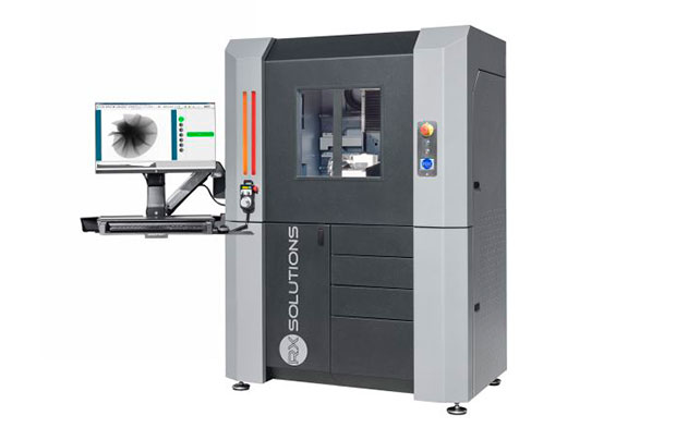
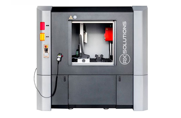
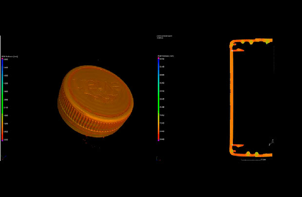
Los resultados proporcionados por la tomografía industrial son muy útiles para el proceso de moldeo por inyección en la industria
El muestreo aleatorio, la creación de prototipos, la inspección de primeros artículos y la optimización de la geometría del molde no tienen los mismos objetivos y necesitan diferentes tipos de análisis. Los sistemas de soluciones de rayos X- CT de RX Solutions de alta calidad pueden brindar una variedad importante de resultados. Incluye informes de metrología, investigaciones de falta de material e inclusiones, análisis de ensamblajes, observaciones de juego y enrase, reparticiones de espesores de pared y estadísticas de orientación de fibras.
Una de las principales aplicaciones de rayos X- CT cuando se habla de la industria del moldeo por inyección de plástico es la optimización del diseño de moldes. De hecho, es una de las tareas más largas a realizar al lanzar una nueva producción de piezas de plástico. La deformación y la contracción deben medirse y tenerse en cuenta para modificar la geometría del molde. Una de las mejores formas de obtener formas internas y externas de un prototipo inyectado es utilizar la tomografía. Es fácil generar una malla tridimensional de toda la pieza, compararla con el modelo CAD y modificar, según las diferencias, el molde relacionado. La comparación de la geometría de la pieza moldeada puede realizarse con un archivo CAD o una muestra maestra, o entre entidades geométricas individuales, entre diferentes moldes, materiales o después de un tratamiento térmico o desgaste.
Otro análisis importante que se puede realizar con rayos X- CT es la prueba de estado del material. Una vez lanzados en las líneas de producción, los principales defectos que se pueden encontrar en las piezas inyectadas de plástico están vinculados a las porosidades debido al aire atrapado durante el proceso y las inclusiones presentes en la materia prima. Ambos se pueden detectar y localizar automáticamente en unos pocos segundos con la tomografía industrial.
La determinación precisa de la superficie interior es posible gracias a una muy buena penetración de rayos X en materiales plásticos. Los fabricantes pueden obtener modelos 3D de sus piezas inyectadas para mejorar los modelos de elementos finitos utilizados para calcular las dimensiones mínimas con el fin de ahorrar la mayor cantidad de material posible. Esta capacidad de medir, con precisión y a lo largo de la pieza, su espesor de pared es única y puede permitir a los ingenieros encargados del diseño ahorrar dinero al reducir el peso de las piezas.
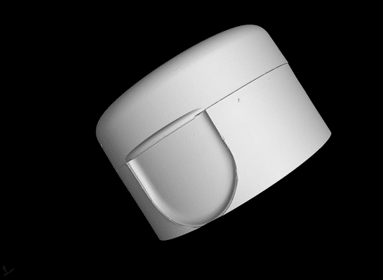
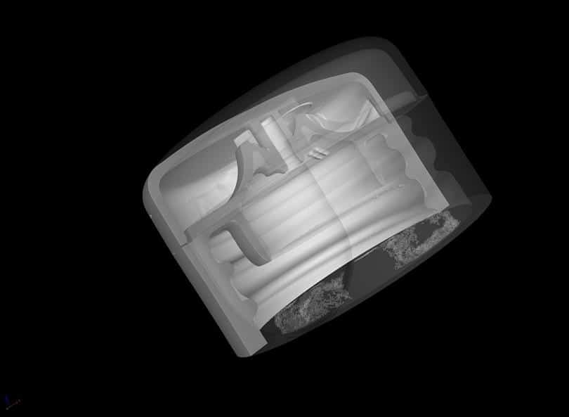
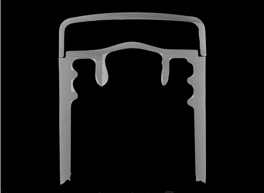
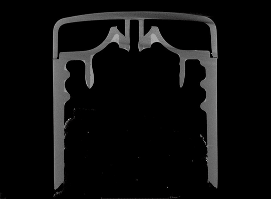
También es posible generar una malla a partir de estructuras externas e internas con bastante facilidad con rayos X- CT. Las nubes de puntos se pueden utilizar como parámetros de entrada dentro de un modelo de elementos finitos, para realizar una comparación con un archivo CAD existente o crear un nuevo CAD mediante un proceso de ingeniería inversa. El análisis de elementos finitos permite que las simulaciones sean más precisas al calcular la tensión mecánica, la deformación, el desplazamiento o el comportamiento del flujo en las geometrías de la pieza real, teniendo en cuenta la falta de material, las porosidades, las inclusiones densas o las grietas.


